Antenna Elevation Calculations (2nd Revision)
© Geoffrey H. Grayer BSc PhD (G3NAQ)
IntroductionIt seems that the formulae necessary to calculate antenna elevation for bi-static contacts via a reflection point are not widely known, certainly in amateur circles. In response to a request by Dave G7RAU I therefore wrote out the derivation of these formulae, and a worked example to demonstrate their use. I hope this proves informative, though as I point out, it is unlikely to be of practical use to any but those with extremely large antenna systems.
My thanks to Victor K6FV for pointing out an error in my original version.
Conventions
Upper case italic letters are used for distances, lower case italic letters for angles, that is all variables are in Italics. Upper case BOLD letters are used for points.
Angles are expressed in radians. Figures are not to scale.
Basic Formula
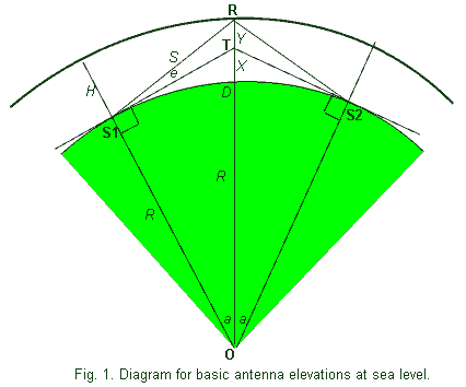
We start by assuming both stations (S1, S2) at sea level, and correct for height ASL later (Fig. 1). There are some limitations to this approach, but these will be shown not to be important. S1-T and S2-T are tangential lines to the surface of the earth, in other words horizontal lines at S1 and S2. O is the centre of the earth. R is the reflection point at height H ASL.

First we define the Great Circle half-angle a as:
a = D / 2R (1)
where D is the surface (Great Circle) distance between the two stations, and
R is the mean radius of the earth.
Next we calculate the height X of point T above sea level by using Pythagoras on the right-handed triangle O-S1-T:
(R + X)2 = R2 + R2 tan2 a
Solving this second-order equation for X by the conventional formula gives:
X = R [v(1 + tan2 a) 1] .. (2)
For simplicity, we now define
Y = H X . . (3)
We can now solve for the distance S between the station S1 and the reflection point R using the triangle S1-R-T:
S 2 = R2 tan2a + Y2 - 2 YR tan ( a ) cos (p/2 + a)
Again solving for this second order equation for S gives:
S = v(R2 tan2a +2RY.tana.sina + Y2) .(4)
Applying the Sine Formula to the same triangle allows us to solve for the sea-level elevation angle e:
sin e / Y = sin (90 a ) / S
which reduces to:
e = sin-1 [Y cos (a ) / S ] ..(5)
Working through equations (1) to (5), you will find all quantities defined.
D, the Great Circle distance between the two stations, may be found by measuring on a suitable map (true distance projection), or by spherical trigonometry from the latitudes and longitudes. R, the mean radius of the earth, is normally taken as 6371 km. H, the effective height of the reflection point, may be taken as 100km for E-layer modes (Ar, ms, Es, FAI). Note that the elevation angles for the two stations are identical until we take their height ASL into account.
Correction for Altitude ASL
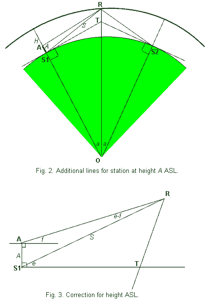
Now consider Fig. 2. The station located at S1 has now been elevated
to point A, at height A above sea level. In Fig. 3 we have drawn for clarity just the triangle A-R-S1. There is a new angle f defining the new (reduced) elevation angle. [Note the approximation made here; we have assumed the reflection point R unchanged, while if S2 is not at exactly the same height, then the reflection point moves to keep incident and reflected angles equal (specular reflection). However, this movement is very small in practice a second order effect on a small correction.]

Applying the Sine Formula to this triangle:
sin ( e - f ) / A = sin (p/2 + f ) / S
From this is the elevation angle f for the station at A is:
f = tan-1 [( S sin e A ) / (S cos e )] .(6)
where e is the elevation angle at sea level, S is the distance from the sea level station to the reflection point, both quantities being calculated above. Note that A must be given in the same units as other dimensions, i.e. kms.
Conclusion
O
The six equations given here can be used for writing a simple program or using a spread sheet to calculate the elevation angle for a spectral reflection to another fixed station. The formula have been checked and are correct; however, whether they apply in any particular case depends on actual parameters. In particular, ground reflections will tend to elevate the beam of an antenna above the angle of the boom, particularly if the polarisation is horizontal; the height of the antenna and the slope of the ground will also effect this angle (refer to Ian White G3SEKs article in RadCom).
Example
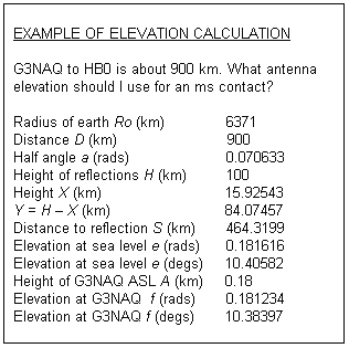
The following is a copy of a calculation using the spreadsheet program Microsoft EXCEL. Cells were programmed according to the formulae listed above, referring to previous cells. Thus to change any of the input parameters, it is necessary only to change the value in the appropriate cell.

This example can be used to illustrate a number of points. First, although the distance is quite short for this mode, the elevation necessary is only just over 10 degs. Given that the 1dB half-beam width in the vertical (H) plane of my 17 el. Yagi is 18.5 degs, and the beam is probably slightly elevated by ground reflections, any advantage would probably be undetectable. Note that correcting for my height ASL (600ft) has no significant effect. Refraction effects in the troposphere have been ignored; it can be shown that even at this elevation angle, the effect is negligible.
To summarise, as I have long advised, for anyone with anything less than an EME array, forget elevation control. The only exception to this is if you have a tall local obstacle, when you should aim your beam just above the skyline to achieve maximum diffraction over the obstacle.
Finally, tropospheric ducting modes take place at low levels (generally in the lower 1-2 km), and the coupling angle to these ducts is unpredictable. One might expect however that it is easiest to enter these ducts at shallow angles (like light entering a light fibre), so again 0 degs elevation is probably usually preferred.